Perception System of Autonomous Vehicles
The visual perception system mainly uses a camera as a sensor input, and through a series of calculations and processing, it can accurately perceive the surrounding environment information of the vehicle. The purpose is to provide accurate and rich information for the fusion module, including the category, distance, speed, and orientation of detected objects, as well as abstract semantic information. Therefore, the perception function of road traffic mainly includes the following three aspects:
- Dynamic object detection (vehicles, pedestrians, and non-motorized vehicles)
- Static object recognition (traffic signs and traffic lights)
- Segmentation of drivable areas (road areas and lane lines)
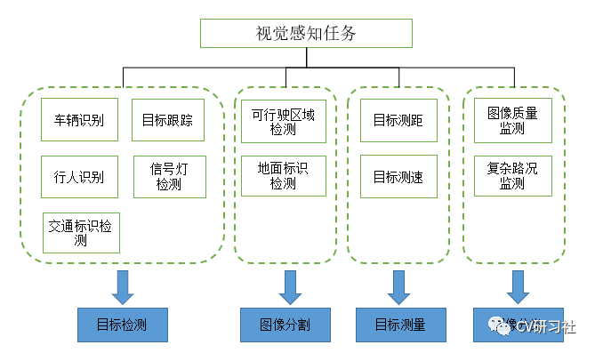
If these three tasks are completed through the forward propagation of a deep neural network, it can not only improve the detection speed of the system and reduce the calculation parameters, but also improve the detection and segmentation accuracy by increasing the number of layers of the main network. As shown in the following figure, visual perception tasks can be decomposed into object detection, image segmentation, object measurement, image classification, etc.
Sensor Components
- Forward linear camera: with a relatively small viewing angle, it is generally installed in the middle of the front windshield of the vehicle using a camera module of about 52°. Its main function is to perceive farther scenes in front of the vehicle, and the perception distance is generally within 120 meters.
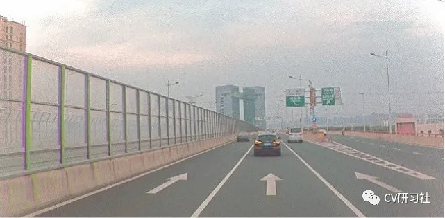
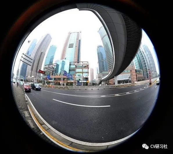
- Surround view camera: with a wider field of view, it usually consists of six camera modules installed around the vehicle at about 100°. Its main function is to perceive the 360° surrounding environment (similar to Tesla’s installation scheme). The wide-angle camera has some distortion, as shown in the figure below:
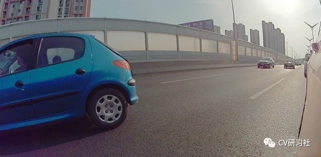
- Fisheye camera: the fisheye camera has a larger viewing angle, which can reach more than 180°, and it is good for close-range perception. It is usually used for parking scenes such as APA and AVP, and is installed in four positions below the left and right side mirrors and the front and rear license plates of the vehicle to complete functions such as image stitching, parking space detection, and visualization.
Camera Calibration
The quality of camera calibration directly affects the accuracy of target ranging, which mainly includes intrinsic calibration and extrinsic calibration. The intrinsic calibration is used for image distortion correction, and the extrinsic calibration is used to unify the coordinate systems of multiple sensors and move their coordinate origins to the center of the vehicle rear axle.# Most Familiar Calibration Method is Zhang’s Chessboard Method
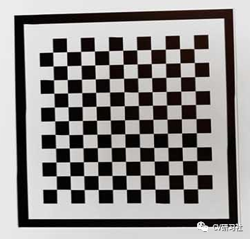
The most familiar calibration method is Zhang’s chessboard method. In the laboratory, a chessboard is usually used to calibrate the camera, as shown in the following figure:
- Factory Calibration
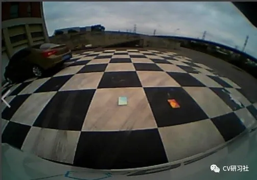
However, due to batch production, it is impossible to use a calibration board for each vehicle calibration in the case of front-end mass production of autonomous driving. Instead, a site is built to calibrate the vehicle during factory production, as shown in the following figure:
- Online Calibration
In addition, considering the deviation of the camera position during vehicle operation for some time or in the process of jolting, the perception system also has an online calibration model, which often uses information detected by vanishing points or lane lines to real-time update pitch angle changes.
Data Annotation
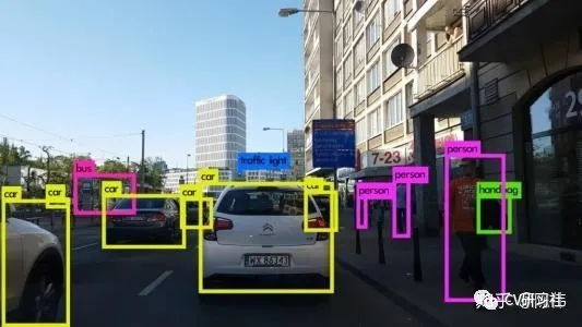
Various sudden situations occur in natural road scenes, so it is necessary to collect a large amount of real vehicle data for training. High-quality data annotation has become a critical work, and all the information that the perception system needs to detect needs to be marked. The marking forms include object-level labeling and pixel-level labeling:
Object-level labeling is as follows:
Pixel-level labeling is as follows:

Since the detection and segmentation tasks in the perception system are often implemented by deep learning, which is a data-driven technology, a large amount of data and label information is required for iteration. In order to improve the efficiency of annotation, a semi-automatic labeling method can be used. The initial labeling can be provided by embedding a neural network in the labeling tool, and then the human can correct it, and after a period of time, the new data and labels can be loaded for iterative cycle.
Function Division
Visual perception can be divided into multiple functional modules, such as object detection and tracking, object measurement, drivable area, lane detection, static object detection, etc.
- Object detection and tracking
Recognizing dynamic objects such as vehicles (sedans, trucks, electric vehicles, bicycles), pedestrians, and outputting the category and 3D information of the detected object, and matching the inter-frame information to ensure the stability of the detection box output and predict the running trajectory of the object. Directly doing 3D regression by a neural network is not accurate enough, so vehicles are usually divided into the detection of multiple parts such as the front, body, rear, and tires combined into a 3D box.## Object Detection Challenges
- There are many occlusions and accuracy issues with the orientation angle.
- There are many types of pedestrians and vehicles, making it easy to have false detections.
- The problem of multi-target tracking and ID switching.
- In terms of visual object detection, the perception performance will decrease to a certain extent in harsh weather conditions. In the dim light at night, it is easy to miss detections. If the results of the laser radar are combined, the recall rate of the targets will be greatly improved.
Object Detection Solutions
- For multi-target detection, especially for vehicle detection, it is necessary to provide 3D Bounding Box, which can provide the orientation angle and height information of the vehicles. By adding a multi-target tracking algorithm, ID numbers can be assigned to the vehicles and pedestrians.
- Deep learning, as a probabilistic algorithm, even if it has a powerful feature extraction capability, it cannot cover all dynamic object features. In engineering development, some geometric constraint conditions can be added based on the real scene, such as fixed aspect ratio of cars and trucks, and limited height of pedestrians. The benefit of adding geometric constraints is to increase the detection rate and reduce the false detection rate, such as cars cannot be mistaken for trucks. A 3D detection model (or a 2.5D model) can be trained and combined with the optimization of the back-end multi-target tracking module and the ranging method based on monocular visual geometry to complete the functional module.
Object Measurement
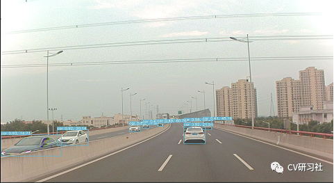
- Object measurement includes measuring the lateral and longitudinal distance, lateral and longitudinal velocity, and other information of the target. Based on prior knowledge and the output of target detection and tracking, the distance and velocity information of dynamic obstacles such as vehicles can be calculated from the 2D plane image or the NN network can directly regress the object position in the world coordinate system. See the figure below:
Challenges of Monocular Ranging
-
How to calculate the distance of the object in the direction from the monocular system that lacks depth information. So we need to clarify the following questions:
-
What are the requirements?
-
What are the priors?
-
What kind of maps are available?
-
What kind of accuracy needs to be achieved?
-
What kind of resources can be provided?
-
If a large amount of pattern recognition technology is relied on to compensate for the lack of depth. Is the pattern recognition robust enough to meet the strict detection accuracy requirements for serial production products?
Monocular Ranging Solutions
- One solution is to establish the geometric relationship between the target world coordinates and the image pixel coordinates through the optical geometry model (i.e. small hole imaging model). By combining the calibration results of camera intrinsics and extrinsics, the distance between the front vehicle or obstacle can be obtained.Task 2:
The second approach is to directly regress the function relationship between image pixel coordinates and distance to the vehicle using collected image samples. This method lacks necessary theoretical support and relies purely on data fitting, thus being limited by the extraction accuracy of fitting parameters and having relatively poor robustness.
Task 3:
The feasible driving area for vehicles can be divided based on the vehicle, the edge of a normal roadside, the edge of a curbstones, invisible boundaries without obstacles, and unknown boundaries. Finally, the safe area that the vehicle can pass through is output.
Difficulty in road segmentation:
In complex environmental scenarios, the boundary shapes are complex and diverse, leading to difficult generalization. Unlike other detection types, such as vehicles, pedestrians, and traffic lights, the space needs to be divided to outline the driving safety area of the vehicle. All obstacle boundaries that affect the vehicle’s driving need to be divided, such as uncommon water horses, cones, potholed roads, non-concrete roads, green belts, boundary tiles, crossroads, and T-junctions.
Calibration parameter correction:
Acceleration and deceleration of the vehicle, road bumps, and ups and downs can cause changes in the camera pitch angle, and the original camera calibration parameter is no longer accurate. When projected into the world coordinate system, there will be significant ranging errors, and the boundary of the drivable space will shrink or open.
Point selection strategy and post-processing of boundary points:
More consideration should be given to the edge of the drivable space, so the glitches and jitter at the edge need to be filtered to make the edge smoother. Boundary points on the side of obstacles are prone to error when projected into the world coordinate system, resulting in the lane next to the front car being recognized as an unpassable area, as shown in the figure below:
Road Segmentation Solution:
1) Camera calibration (if online calibration is achievable, it is better, but the accuracy may be discounted). If online calibration cannot be achieved, IMU information from the vehicle can be read to adaptively adjust the calibration parameters based on the pitch angle obtained from the IMU information.
2) Select a lightweight and appropriate semantic segmentation network to label the categories that need to be segmented, covering the scenarios as broadly as possible. Polar coordinate point selection is used for sampling and filtering algorithms are used to smooth out the edge points.
Task 4:
Lane detection includes the detection of all types of single/double lane lines, solid lines, dashed lines, double lines, and the detection of line colors (white/yellow/blue) and special lane lines (convergence lines, deceleration lines, etc.), as shown in the figure below:
Difficulty in lane detection:The difficulty of detecting lane markings with multiple line types and irregular road surfaces is high. Lane markings are also prone to false detection and missed detection in cases of standing water, invalid signs, repaired road surfaces, and shadow conditions.
On uphill, bumpy roads or during vehicle start-stop, lane markings can be detected as trapezoids or inverted trapezoids.
For curved, distant, or roundabout lane markings, the difficulty of fitting them is higher, making detection results more prone to flickering.
Lane detection methods:
First, traditional image processing algorithms require camera distortion correction, perspective transformation for each frame to convert the photo taken by the camera into a bird’s-eye view. Lane features are then extracted using feature operators or color spaces, and the lane curve is fitted using methods such as histogram and sliding window. The biggest drawback of traditional methods is poor scene adaptability.
Second, neural network methods are used to detect lane markings similar to how passable spaces are detected. A suitable lightweight network can be selected, and labels can be applied. The difficulty in lane detection lies in fitting the lane curve with a cubic or quartic equation. Therefore, post-processing can combine vehicle information (speed, acceleration, steering) and sensor information to perform navigation calculation and improve fitting results as much as possible.
- Static object detection
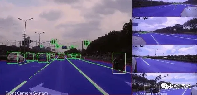
Static object detection includes the detection and recognition of static targets such as traffic lights and traffic signs, as shown in the figure below:

The difficulties of static object detection:
Traffic lights and signs are considered small objects, and they occupy very few pixels in the image, especially in long-distance intersections, making recognition more difficult. Even the human eye has difficulty identifying them under strong light. Stopping at a zebra crossing in front of the car requires correct recognition of traffic lights to make further judgments.
There are numerous types of traffic signs, and data acquisition can easily result in uneven quantities.
Traffic lights are sensitive to light and have poor color discrimination under different lighting conditions (red lights and yellow lights). Moreover, at night, the color of the red light is similar to the color of the roadside lamps and store lights, making false detection easy.
Static object detection solutions:
Perception can be used to recognize traffic signals, but its effect is general, and its adaptability is poor. If conditions permit (such as in fixed park-limited scenarios), V2X/high-precision maps and other information can be used. Multiple backup redundancies are recommended, in which V2X > high-precision maps > perception recognition. If GPS signals are weak, prediction can be made based on perception recognition results, but in most cases, V2X is sufficient to cover many scenarios.
Common problems
Although the implementation of perception subtasks is independent of each other, their upstream and downstream dependence and algorithmic commonality problems include:
(1) True-value sources. Definition, calibration, analysis, and comparison are not based on detection result charts or frame rates. Instead, laser data or RTK data are considered true values to verify the accuracy of distance measurement results under different working conditions (daytime, rainy, obstruction, etc.).(2)Resource utilization. Multiple networks coexisting, multiple cameras sharing will consume CPU and GPU resources. How to allocate these networks effectively and reuse some convolution layers to achieve efficient coordination of each functional module by introducing concepts from threads and processes. In terms of multiple camera inputs, it is necessary to achieve multi-target input without losing frame rate and work on camera stream encoding and decoding.
(3)Multi-camera Fusion. Usually, four cameras (front, rear, left, and right) are equipped in cars. When the same object moves from the rear of the car to the front, it can be captured by the rear-view camera, the side-view camera, and finally the front-view camera. In this process, it’s important to ensure the object ID remains unchanged regardless of camera changes, and the distance information should not jump too much when switching between different cameras.
(4)Scene Definition. For different perception modules, data sets, and scene definitions need to be explicitly divided to make algorithm validation more targeted. For example, dynamic object detection can be divided into detection scenes for static vehicles and moving vehicles. For traffic light detection, it can be further divided into specific scenes such as turning, straight, and turning around. Verification of commonly used and proprietary data sets.
Module Architecture
Currently, open-source perception frameworks, such as Apollo and Autoware, are often referenced by researchers or small and medium-sized companies in the development of their own perception systems. Therefore, the module composition of the Apollo perception system is introduced here.
Camera input –> Image pre-processing –> Neural network –> Multiple branches (red and green light recognition, lane recognition, 2D object recognition to 3D) –> Post-processing –> Output results (output object type, distance, and speed representing the direction of the detected object).
That is, based on each frame of information, the input camera data is used for detection, classification, and segmentation calculation. Finally, multiple frames of information are used for multi-target tracking and related results output. The entire perception flowchart is as follows:
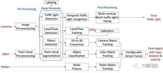
The aforementioned core link is still the neural network algorithm, and its accuracy, speed, and hardware resource utilization are all indicators that need to be considered and balanced. It’s not easy to handle each link well because object detection is prone to false positives or false negatives, lane detection requires fitting a 4th-degree equation curve, and detecting small objects such as traffic lights is difficult (the length of the road junctions is often over 50 meters). Additionally, the boundary point of the passing space has high requirements.
This article is a translation by ChatGPT of a Chinese report from 42HOW. If you have any questions about it, please email bd@42how.com.
