Volkswagen provided a self-study manual “Self Study Program 811213 The High-Voltage System in the ID.4” to the U.S. NHTSA, which contains information on batteries. Here, I will supplement some interesting information that has not been previously mentioned.
EV Control Network
J533 is a control module developed by Continental for Volkswagen, a Data Bus on Board Diagnostic Interface ICAS1. What’s special here is that Volkswagen has divided the high-voltage electrical components into two networks for management.
CAN-EV Network: This includes J979 air conditioning control module (with two J842 compressor boxes and one J848 PTC), J840 battery main control management module, which includes three controllers that communicate through a sub-CAN network with Z132 water-cooled PTC boxes. J1050 is an independent on-board charger, A19 is a DCDC converter, and these components are all centered around the battery and familiar systems.
Powertrain CAN Bus: Volkswagen has established an independent J841 motor control module and a J623 similar to the vehicle control module.
Usually, all of these are handled in one network, but Volkswagen has modularized them.

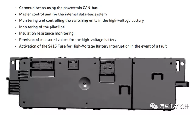
This BMS, Lin controls the PTC, manages the internal network with CAN, and communicates externally. There is also a Pilot Line maintenance switch and insulation resistance detection inside, and the most critical thing is to control the PyroFuse of S415 to cut off the system.

Interior BDU Design
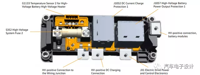
This figure shows how the two parts of the BDU are connected. Volkswagen’s engineers really arranged the main positive side and the main negative side separately in terms of mechanical layout, and then directly connected them to the external connector after bridging them with a copper plate for output.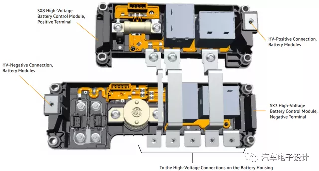
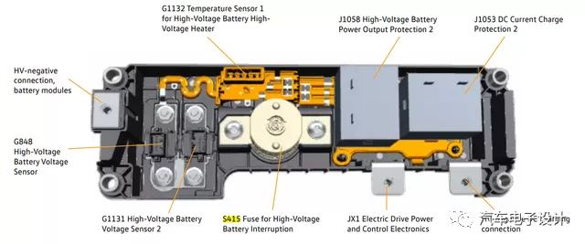
The output of the main circuit negative pole is directly connected to the negative poles of external inverters and DC fast chargers through contactors. Several connectors are mainly equipped with temperature and voltage sensors, and the negative pole here is equipped with the PyroFuse S415.
The S415 Fuse for High-Voltage Battery Interruption is a pyrotechnic fuse and improves the safety of the high-voltage system. In case of a fault, it can trip faster than a high-voltage relay. If it has tripped, the entire SX7 unit must be replaced; it cannot be reset.
The module designed here is replaceable, and the negative pole distribution module SX7 can be directly replaced.
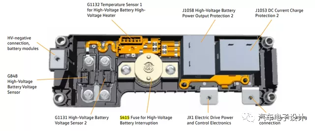
It is strange that there are two independent temperature sensors for the G1133 and G1132 high-voltage battery heaters, which may be used to detect the temperature of Z132. The fuse below is a system output that is used for the auxiliary system of the junction box.
Conclusion: The biggest feature of the MEB system is its excessive modularity and low integration, and the centralization of the control-decentralization software is not high. Overall, although MEB has introduced a domain controller, the approach to the control and integration of the entire high-voltage system seems to be the opposite.
This article is a translation by ChatGPT of a Chinese report from 42HOW. If you have any questions about it, please email bd@42how.com.
