*Author: Empowering Manufacturing with Technology
The development of next-generation autonomous driving technology is already in full swing in relevant fields, especially in several key areas where development of autonomous driving is becoming increasingly urgent. In a previous article, we analyzed the design solutions for the architecture of next-generation autonomous driving products in detail, including chip-level, architecture connectivity, hardware selection, and other aspects.
However, autonomous driving involves a wide range of fields. This article will focus on several currently popular fields, aiming to provide corresponding support for the development of autonomous driving technology. These major areas include large-scale fault data recording and environmental data collection, as well as system-level functional safety design and logic error verification. In addition, setting up a safety path for system failure is also a major challenge.
The following content will explain each of these areas in detail.
Advanced Autonomous Driving Data Acquisition Technology
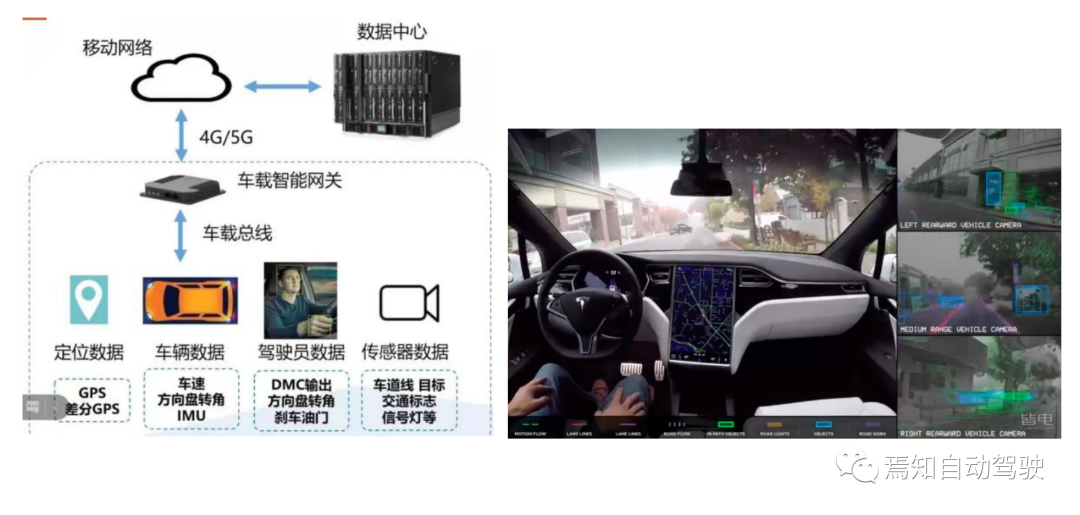
The data acquisition technology of autonomous driving is already familiar, and the more intuitive recording method is to collect video information in a similar way to a driving recorder.
However, the difference is that the video information collected in autonomous driving includes actual detected front road video, surrounding panoramic video, rear video, etc. This recording method directly stores the data sent by the vehicle’s visual sensors (such as front view cameras, panoramic cameras, and rear view cameras).
The environmental data collection scheme for the next-generation autonomous driving system will focus on the following types of scenarios:
1) Event Triggered Acquisition Record: That is, when specific events occur, the complete record of several seconds before and after the event is directly recorded.

This is also a commonly used recording type in autonomous driving data acquisition technology. It is generally used for direct traceability and scene reproduction of special situations or faults, so as to analyze the cause of the accident and identify accident responsibility.
2) Specific Location Acquisition Record: That is, the data is recorded completely after the vehicle has driven to specific locations.

This type of autonomous driving data acquisition technology is mainly aimed at recording specific scenes. By continuously recording various driving states under various autonomous driving conditions, relevant autonomous driving data can be continuously collected, and finally the data under the specific location can be complete, which is used for autonomous driving development and simulation testing.
3) Shadow Mode Acquisition Record: The system continuously records various data when driving, including specific driving behavior data of the driver when driving the vehicle, but does not include the original video, such as the depth of throttle or brake pedal, the rate of throttle or brake pedal, turning speed, and turning angle.Here I need to emphasize the way of collecting and recording data in the “Shadow Mode”. The “Shadow Mode” was first proposed by Tesla, which means that the sensors of the car are still in a standby state while the driver is in the process of driving, and continuously running the algorithm of autonomous driving in the “shadow”. Through certain comparison algorithms, it can be determined which is more efficient and better in performance between autonomous driving and human driving.
The core of the “shadow mode” is that the system, including sensors, is still running but not controlling while in the human driving state, and is used to run the algorithm model and verify it.
The autonomous driving algorithm makes continuous simulation decisions in the “shadow mode” and compares the decisions with the driver’s behavior. When the driver’s driving behavior is completely consistent with the autonomous driving system control behavior, the system maintains the current control state without changing it. When there is a difference between the driver’s driving behavior and the autonomous driving control behavior, two situations will arise:
The first is when the difference is too large, it is judged that the driver’s driving process may have a problem, and the system will issue a warning to the driver; if the driver steps on the accelerator too fast and with a certain depth, the system will judge that the driver may mistakenly step on the accelerator as the brake pedal, and issue a warning to inform the driver that the current operation is a mistake.
The second is when the difference is relatively small, which indicates that the autonomous driving algorithm itself is not perfect enough and needs to learn new automatic control strategies from the current actual driving situation.
For example, in a certain working condition, the system determines that it needs to slow down, so it slows down at a relatively large deceleration rate, resulting in a large distance between the vehicle and the preceding vehicle when following it, and this working condition cannot fully meet the performance requirements of autonomous driving.
Therefore, the system needs to learn from the actual depth and rate at which the driver steps on the pedal in this working condition, which is more consistent with the target expectation. As a result, the acceleration sent by the system later will try to imitate the driver’s acceleration and deceleration rate and speed.
The two typical application solutions for collecting data in the “Shadow Mode” are as follows:
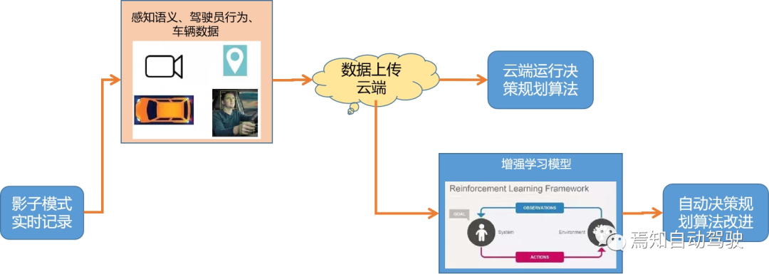
A) Reinforcement learning scheme based on “Shadow Mode”

This reinforcement learning method mainly records data in real-time through the “Shadow Mode”, and then generates information such as perceptual semantics, driver behavior, and vehicle data, which are subsequently uploaded to the cloud. The decision-making and planning algorithms are run in the cloud to train the reinforcement learning model and finally automatically improve the decision-making and planning algorithms.
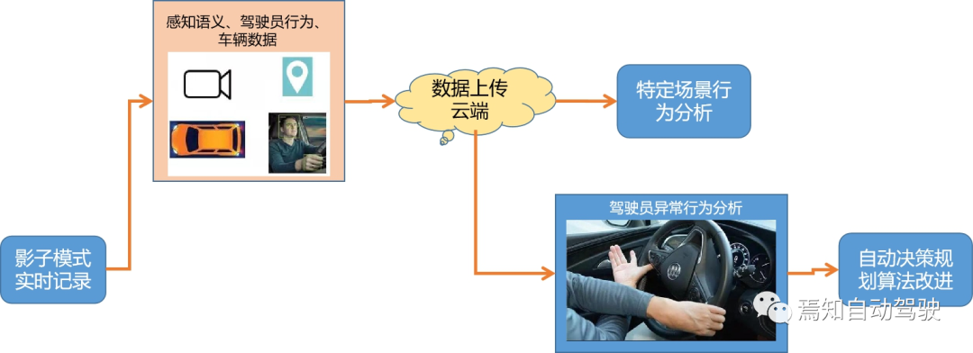
B) Decision planning training scheme based on “Shadow Mode”
 The method of reinforcement learning mainly involves real-time data recording through shadow mode to generate perception semantics, driver behavior, vehicle data and other information, which is then uploaded to the cloud for specific scenario driving behavior and abnormal driving behavior analysis and learning, and eventually improved decision-making planning algorithms.
It is important to note that a judgment logic standard needs to be set within the shadow mode. This standard is higher than the existence of the driver and the machine and is used to evaluate who has better control, thereby helping the autonomous driving algorithm for future optimization control.
Therefore, to ensure the effectiveness of the shadow mode for optimizing the autonomous driving algorithm, it is necessary to ensure that its judgment standard is optimal, otherwise misjudgments may cause incorrect adjustments to the driving behavior parameters.
4) Specific data collection recording: The system records the following specified collection data as required:

This specific data collection recording method is generally carried out under specific conditions, such as automatic driving requiring that the basic data of high-precision map building be processed in the central control chip, which requires separate collection and processing of these specific data for the domain controller to directly extract data for modeling and calculation. Ultimately, the map data is better able to reflect the real driving environment.
Functional Safety Design Requirements – Logic Error
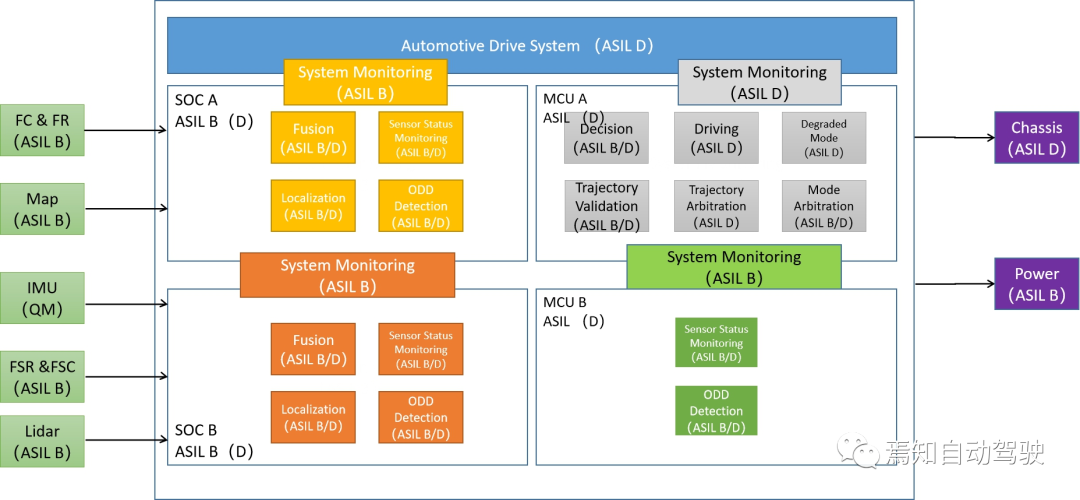
In the functional safety design of autonomous driving systems, the allocation of functional safety requirements for hardware-level controllers and sensors is generally the focus. However, there are no consistent solutions for the software algorithm design issues in the system functions. The software algorithm design here includes three main parts:
1) AI algorithm design based on SOC processing:
The AI algorithm design based on SOC processing is mainly aimed at sensor data processing. As the central brain for perception data processing, the main computing tasks of the front-end SOC chip include processing of raw target data, data fusion, and target positioning.
2) Logic algorithm design based on MCU:
In addition, for the MCU as the center of logical operations, the main tasks include decision control, trajectory verification, trajectory arbitration, mode arbitration, mode degradation, driving, etc. Among them, decision-making and trajectory verification need to be redundantly designed between two MCU control chips.
Other software module functional safety requirements besides planning and decision-making and trajectory prediction need to meet ASIL D level.
3) System monitoring and management algorithm design:
For the entire system monitoring process, it mainly includes monitoring of sensor data processing and monitoring of logic control process. In addition, monitoring of data transmission link is also essential to ensure the effectiveness and availability of data communication.4) Design and Run Range ODD Detection:
The operational safety integrity level (ASIL) requirement for the computational functions of the SOC chip mentioned above must meet or exceed ASIL B level, and the overall implementation must meet the ASIL B+ safety level requirement.

For the processing of sensing data by the entire AI chip and logical data by the MCU, it is essential to consider the different functional safety requirements of the two. In an autonomous driving system, the control process must achieve the highest safety level, ASIL D.
The key to designing functional safety for the aforementioned levels is to consider the safety strategy for controlling the vehicle in practice.
Typically, for perception data processing, the varying hardware safety standards of each sensor can result in deviation in the processing results of the entire system.
In general, the functional safety of the perception end’s software is typically ASIL B or ASIL D. If the SOC does not include a functional safety island for processing sensing data, the functional safety level will generally only achieve ASIL B. However, if the SOC includes a functional safety island for processing sensing data, the entire software can continuously utilize a lock-step method for safety verification.
Moreover, the logic control of the MCU needs to be responsible for the vehicle control of the entire system, requiring a sufficiently high functional safety level (ASILD) to ensure that when the perception capabilities are insufficient to meet high-level functional safety requirements, the deficiencies can be compensated for during planning and decision-making in the control execution end.
At the same time, redundancies need to be checked for during planning, decision-making, and trajectory verification in the MCU’s safety design.
In terms of the functional safety requirements of related systems, the hardware side of the sensors generally requires ASIL B+ or higher. This is especially true for detection targets, such as cameras and radars, which require greater precision and higher recognition rates.
Therefore, the sensor requirements may reach ASIL C or even D, while for positioning systems, because of their inherent flaws, they may be unable to meet high safety levels, thereby generally only requiring ASIL A or lower levels like QM.
On the other hand, for actuators such as steering units and brake units, their functional safety levels generally need to reach ASIL D. Only this setting process can ensure the peripheral control further meets the ASIL D safety level requirements.
System Failure Safety PathWhen designing autonomous driving systems, system failures are a common issue. System failures mainly include sensor failures, autonomous driving domain controller failures, power supply failures, and software logic failures. In addition, system unavailability and vehicle driving exceeding ODD are also considered as system failures.
For the solution to various failure paths, the following methods are mainly used:
1) Sensor failure – It is necessary to first determine the impact of the failed sensor on the entire autonomous driving system, and select different autonomous driving system processing paths based on the results of different degrees of determination.
There are several typical processing paths:
① Can maintain L3 function activation and normal control of the vehicle.
② Downgrade to L2.5 function and prompt the driver to take over after a certain period of time.
③ Downgrade to L2 function and prompt the driver to take over after a certain period of time.
The corresponding failure reason scene map is as follows:
Firstly, the system needs to determine whether both redundant processing paths are in a safe state when the sensor fails. If so, normal L3 driving function is still maintained. If only one path is available, the safety control algorithm of the driving function on that path is turned to ensure that the autonomous driving system controls the vehicle to stop safely when the sensor fails.
2) Controller failure – This process is generally determined by first judging whether L3 normal control path can still control the vehicle for autonomous driving through the above-mentioned safety path. If the failed controller does not affect controlling the vehicle for normal autonomous driving, the normal L3 autonomous driving function is maintained. Otherwise, the redundant safety control strategy is turned on to control the vehicle for safe stopping in the same lane or at the side of the road.
Summary
There are several important technical areas in the design of next-generation autonomous driving, including system architecture design, data parameter collection, and system failure degradation strategy design. Each of these fields has corresponding design rules, and in the process of system development, we need to pay attention to how to effectively design and apply while ensuring the development objectives.
This article is a translation by ChatGPT of a Chinese report from 42HOW. If you have any questions about it, please email bd@42how.com.
