Author: Li Jing
Introduction
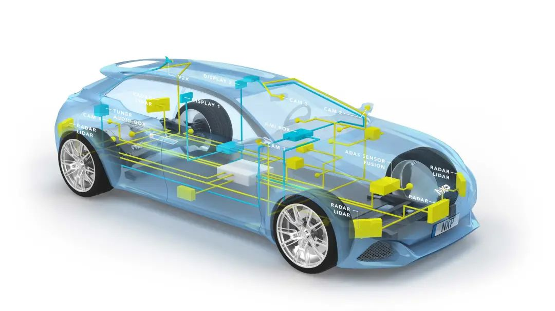
Recently I had the honor to attend the “2021 Intelligent Automotive Electronic and Electrical Architecture and Software Developer Conference” hosted by NIO automobile. At the conference, IntrepidControl Systems shared the topic of “Testing Scenarios and Solutions for In-Vehicle Ethernet”, which gave me numerous inspirations and thoughts. It is well-known that the development of automotive electronic and electrical architecture, new software architecture, and in-vehicle network has been advancing rapidly in recent years, and we, the practitioners working in the field of automotive electronics, are the ones who have experienced this change most profoundly. This rapid development of technology in the past few years has been primarily driven by the trends of intelligent, connected, electric and shared automobiles. Vehicle Ethernet technology plays a crucial role in supporting these trends. In this article, I will present a brief summary of Vehicle Ethernet technology from both its reasons and technology aspects.
Reasons
The Transformational Demands of New Electronic and Electrical Architecture
Firstly, the trend of new 4s in the automotive industry is leading to the transformation of the electronic and electrical architecture. The current distributed architecture with dozens or even hundreds of electronic control units (ECUs) connected to various buses has always followed the pattern of “one function, one box”. Under this distributed architecture, every time a complex function is added, multiple relevant controllers need to be upgraded, leading to increased communication and maintenance costs, and further incrementing the complexity of the entire system.
With the development of the new 4s, the proportion of software value in automobiles is increasing dramatically. For example, in terms of software code lines (SLOC) contained in today’s automobiles, it was only around 10 million SLOC for mainstream models in 2010, whereas it had reached around 150 million SLOC by 2016. Facing the increase in automobile functionality and software complexity, electronic and electrical architecture must transform in advance. Therefore, the concept of domain control has become increasingly popular in recent years, where the entire car is divided into different domains, such as the powertrain, body, chassis, entertainment and other domains, with each domain only mounting a single controller to be responsible for the functions of that domain. This approach reduces the number of controllers and network topology complexity of the entire vehicle. In recent years, technology such as multi-core heterogeneous chips, hypervisors and others have provided hardware and software support for the development and application of domain control.
As the integration of functions continues, hardware computing capabilities advance, and advanced sensor technologies develop, the entire vehicle architecture will move toward central computing units.
The transformational demands of new electronic and electrical architecture require support from in-vehicle Ethernet technology.### Introducing Service Oriented Architecture (SOA) Communication on Top of Signal Based Communication
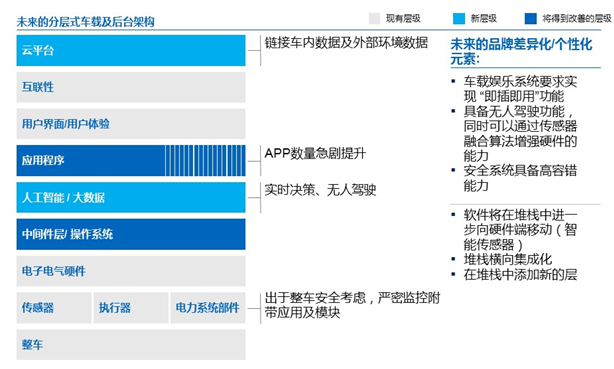
Future cars will become platforms that carry new differentiated elements, which may include the latest in-vehicle entertainment systems, self-driving and intelligent safety features based on “high fault tolerance”. Software will integrate with hardware through intelligent sensors, and delve even deeper into the digital stack. The stack will be horizontally integrated and new layers will be added, transforming the overall structure into SOA.
Signal based communication is currently widely used in vehicle bus, such as the transmission of information between controllers through CAN bus, which is a typical signal-based communication.
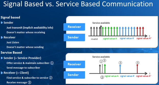
SOA is a software architecture, as well as a software design method and concept, which has been applied in the IT field for decades. SOA features “loose coupling”, “interface standards accessibility” and “ease of extension”, which enables developers to respond to iterative and changing customer needs with minimal software changes. The introduction of SOA in cars is mainly due to the following advantages:
-
High service cohesion and easy software reuse.
-
Flexible deployment of services.
-
Faster and more efficient software update and upgrade.
Based on the above introduction, the signal-based communication method supports simple data types and has poor scalability, which is suitable for application scenarios with limited data exchange sizes. However, with the addition of advanced applications such as self-driving, dynamic interaction of large amounts of data must be carried out using service-oriented communication to improve communication speed and efficiency. Therefore, the overall vehicle communication must introduce SOA communication support on top of signal-based communication. The support of SOA requires vehicle Ethernet technology.
Vehicle Ethernet will become the backbone of the overall vehicle communication network
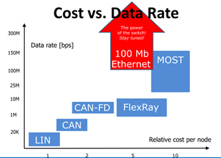
Due to the increase in complexity of the car’s E/E architecture and functions, and the demand for increased bandwidth and communication method changes (service-oriented communication – SOA), Vehicle Ethernet will gradually become the backbone of the vehicle bus.
 How is the Ethernet in the car different from the Ethernet we normally come into contact with, given its special application scenarios? Below, I will briefly introduce the OSI seven-layer network model when introducing the network layer model of car Ethernet. (OSI=OpenSystems Interconnection), which is an important model in the development of the Internet. As an ideal network reference model, the TCP/IP model has been widely used as a network layer model for the Internet. The TCP/IP model does not strictly distinguish between the 5-7 layers of OSI and collectively refers to them as the application layer.
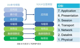
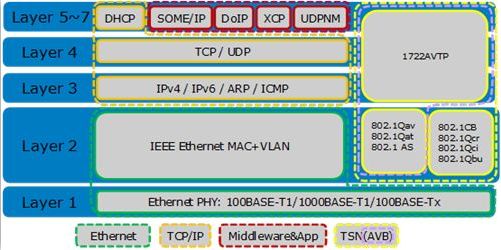
Car Ethernet is based on the TCP/IP network layer model, and Ethernet-related protocols have been standardized and supplemented by alliances such as OPEN and AUTOSAR.
Physical connections of car Ethernet: From a hardware perspective, the Ethernet interface circuit is mainly composed of two parts: the MAC (Media Access Control) controller and the physical layer interface PHY (Physical Layer, PHY). The MAC and PHY work in the data link layer and physical layer of the OSI seven-layer model. How do PHY and MAC transmit data and communicate with each other? The MAC and PHY are connected through two interfaces, namely the SMI interface and the MII interface.
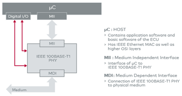 MII (Media Independent Interface) is a standard interface that connects the MAC and PHY in Ethernet. The MAC sends data frames through this interface, which are transmitted to other network nodes after being processed by the PHY. Data from other network nodes is also processed by the PHY before being received by the MAC. MII is an Ethernet industry standard defined by IEEE-802.3. The interface provides interconnect technology between MAC and PHY and between PHY and STA (Station Management). The interface supports data transfer rates of 10Mb/s and 100Mb/s, with a data transfer width of 4 bits. The term “media independent” indicates that any type of PHY device can function normally without redesigning or replacing MAC hardware. The 802.3 protocol supports a maximum of 32 PHYs, but with some limitations: the connector characteristics must comply with protocol requirements.
SMI (Serial Management Interface) is an interface that allows the Ethernet MAC to access PHY registers for control and management purposes. The SMI interface includes MDIO (for controlling and managing PHY in order to obtain its status) and MDC (for providing a clock to MDIO). MDC is provided by the MAC, while MDIO is a bidirectional data line used to transmit control information from the MAC and physical layer status information. The MDIO data is synchronized with the MDC clock and is valid on the rising edge of MDC.
As such, MAC and PHY, one is the data link layer while the other is the physical layer, transfer data through the MII. Hence, the Ethernet interface essentially involves the MAC controlling the PHY through the MII bus.
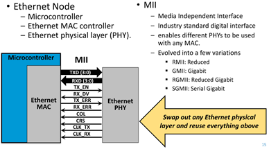
MII interface has spawned many other versions, such as RMII, GMII, SGMII, RGMII, etc. Here, we briefly introduce MII and RMII as shown in the following diagram. MII uses 16 wires in total, and CRS and COL are only valid in half-duplex mode. In contrast, Ethernet in automotive environments operates in full-duplex mode, so 14 wires are required.
RMII is a simplified version of MII that uses only two wires for data transmission and reception, reducing the number of wires by four. Additionally, it integrates or eliminates some wires. Ultimately, RMII uses only 8 wires, as shown below:
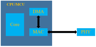
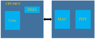
In actual design, these three parts are not necessarily separate. Due to the integration of a large number of analog hardware in PHY, and MAC is a typical all-digital device. Considering chip area and analog/digital hybrid architecture,usually, MAC is integrated into the microcontroller while PHY is left off-chip. More flexible and higher density chip technology has made it possible to integrate MAC and PHY into a single chip. They can be divided into the following types:
CPU integrated MAC and PHY, which is currently not common:
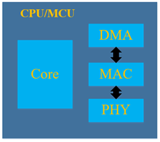
CPU integrates MAC, and PHY uses a separate chip. This is the mainstream way in automotive Ethernet because embedded chip manufacturers usually integrate MAC inside the MCU, while PHY chips are selected by OEM or controller suppliers by themselves:
CPU does not integrate MAC and PHY, and MAC and PHY use an integrated chip. This is more common in consumer Ethernet, such as computer network cards.
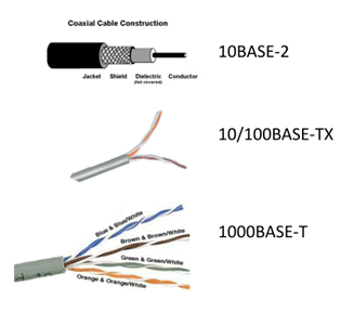
In Ethernet connection harnesses, automotive Ethernet and consumer Ethernet are also different. First of all, consumer Ethernet standards mainly use 10BASE-2, 10/100BASE-TX and 1000BASE-T. Among them, 1000BASE-T uses the RJ45 interface, which requires eight wires of four pairs of twisted pairs to transmit data, while 10/100BASE-TX only uses two pairs of twisted pairs of the four pairs, totaling four wires to transmit data. The following is a schematic diagram of 100BASE-TX (using two pairs of twisted pairs). In the early 10BASE-2, coaxial cable was used to transmit data. Therefore, the wiring harnesses for consumer Ethernet are summarized as follows:
 The Ethernet used in vehicles generally adopts standards with T1, such as IEEE 100BASE-T1 (formerly known as OABR) and IEEE 1000BASE-T1, which use a pair of twisted-pair wires to transmit data using two wires in total.
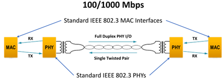
As shown above, the Ethernet used in vehicles mainly adopts the 100BASE-T1 or 1000BASE-T1 standard based on a pair of twisted-pair wires for data transmission, while our computers use the 1000BASE-TX standard based on four pairs of twisted-pair wires for data transmission through the RJ45 interface. Therefore, when we measure the controller Ethernet with a computer, we need a converter, as shown below:

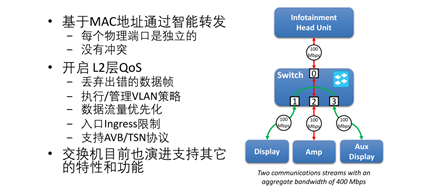
Vehicle Ethernet is a point-to-point communication. When multiple nodes of the vehicle Ethernet are interconnected and require communication, a switch is needed. The role of the switch is as follows:
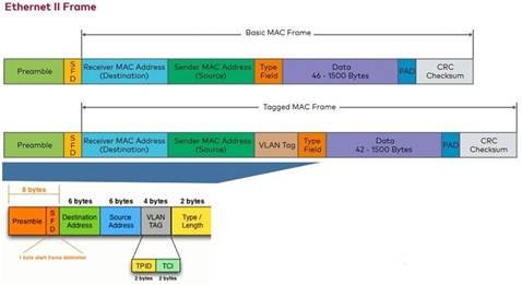
Frame structure of vehicle Ethernet: The Ethernet frame format is as follows:

There are multiple types of Ethernet frames, which have different formats and MTU values. However, different types of frames can coexist on the same physical media. There are two common frame formats: the first is the DIXv2 format proposed in the early 1980s, namely the Ethernet II frame format. Ethernet II was later adopted by the IEEE 802 standard and included in section 3.2.6 of IEEE802.3x-1997. The second is the IEEE802.3 format proposed in 1983.
The main difference between these two formats is that the Ethernet II format includes a Type field, indicating which upper layer protocol the Ethernet frame should be sent to for processing after completion. In the IEEE802.3 format, the same position is the length field.
The automotive industry usually uses the Ethernet II format, which can also include VLAN information as an extension. Therefore, there are two types of MAC frames, basic MAC frames (without VLAN) and tagged MAC frames (including VLAN).
The transmission process of Ethernet frames in vehicle: As we mentioned before, vehicle Ethernet is based on the TCP/IP network model. Therefore, we do not consider which application layer protocol the application layer data is organized based on. The data from the application layer will add TCP/UDP headers after the transport layer, then IP headers at the network layer, and then add MAC addresses and other information at the link layer. Finally, it will be converted into binary streams on the line by PHY to achieve data transmission between the sender and receiver.
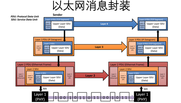
TCP protocol is at the transport layer and IP protocol is at the network layer. There are many application layer protocols, and the main ones for vehicle Ethernet are AVB/TSN/DoIP and SomeIP.
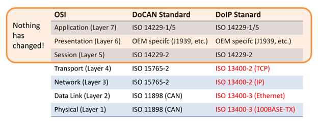
Firstly, DoIP or Diagnostics over IP, we are most familiar with DoCAN. The protocol differences are not significant, mainly in two aspects:
-
Replacing ISO 11898 (CAN) with Ethernet
-
Replacing ISO 15765-2 with TCP/IP
AVB is mainly used for streaming media data transmission. Streaming media data transmission must be in the correct order (must be represented in order) and be timed correctly (cannot timeout). In addition, AVB has the advantages of flexibility, standard development, wide acceptance, and can operate on any Ethernet PHY.
AVB is only for streaming media, but emerging technologies support ADAS and autonomous driving vehicle demand far more than that of streaming media. Therefore, in order to adapt to the development trend of automobile intelligence, there is TSN.
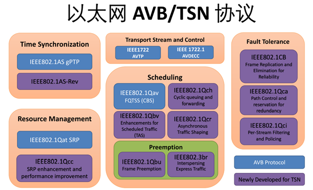
Therefore, vehicle Ethernet is continuously evolving to meet the requirements of future application scenarios on its existing basis. At the same time, testing technology for vehicle Ethernet will become increasingly important. For example, the products introduced by the Hungarian company Intepes Control Systems cover various testing equipment scenarios for Ethernet.
ConclusionThe increase of data amount, OTA updates, redundant requirements of HAD, security guarantee in the interconnected environment, and the demand for cross-industry standard protocols will drive the rapid development of automotive Ethernet and make it a key propelling factor for redundant central data buses. Ethernet solutions enable cross-domain communication and meet real-time requirements by adding Ethernet extensions such as Audio-Video Bridging (AVB) and Time-Sensitive Networking (TSN).
Traditional networks such as Local Interconnect Network and Controller Area Network will continue to be used in vehicles but only for closed lower-level networks such as sensors and actuators. Technologies such as FlexRay and MOST may be replaced by automotive Ethernet and its extensions such as AVB and TSN. “Automotive Ethernet” will become an essential part of the vehicle in the future.
This article is a translation by ChatGPT of a Chinese report from 42HOW. If you have any questions about it, please email bd@42how.com.
