*Author: Aimee.
The current design approach of mass-produced autonomous driving systems generally utilizes a multi-radar and less-camera scheme, primarily due to considerations regarding the computing power of the autonomous driving chips. However, relying solely on a multi-radar detection scheme often cannot fulfill performance requirements, such as for detecting certain road environment targets (e.g., vehicle types, lane markings) and detailed environmental detection (e.g., signage, small lane targets), which must rely on cameras for effective detection. In the next-generation autonomous driving systems, once the design of the central domain controller can fully cover the chip’s computational power and bandwidth requirements during its overall operation process, our goal is to achieve full coverage with multi-camera installations to achieve 360-degree omnidirectional environmental detection capability without dead zones. The corresponding camera installation scheme also needs to be fully designed. This article will elaborate on the detailed explanation of the camera installation design scheme, software information processing scheme, and performance indicator design scheme for the next-generation autonomous driving system, with the aim of providing readers with a detailed explanation of the camera scheme.
Background Overview
From the hardware architecture perspective, the currently announced mass-produced autonomous driving system plan mostly adopts the 5R1V1D architecture (except for the Tesla camera series), which relies on a single camera and a millimeter wave radar for forward detection, with a primary detection target type of vehicles and the current lane markings. Side detection relies on four millimeter wave radars, with the primary detection target type being vehicle targets. However, this type of installation method often fails in the following extreme scenarios:
Forward target detection:
During forward detection, because the basic target image output is mostly consistent, in layman’s terms, in many cases, it is a detection type that cannot change the image size. This results in insufficient detection distance when the image resolution is too low to detect small targets at long distances, and when the image resolution is too high, its FOV is insufficient to respond quickly to targets suddenly cutting into the current lane.
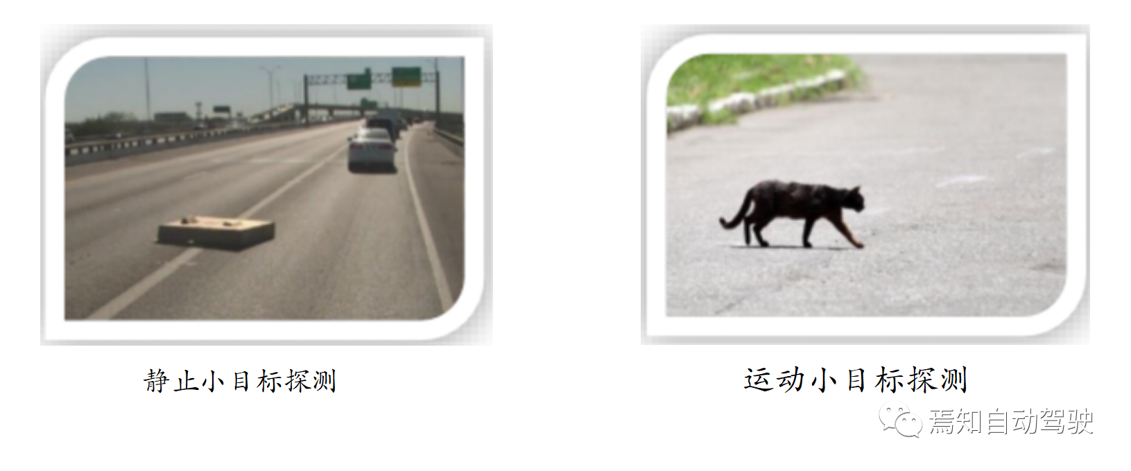
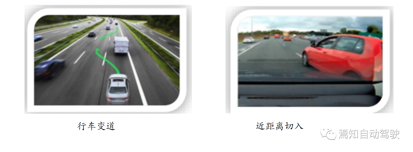
Side target detection:
In side detection, the millimeter wave radar technology currently used is mainly applied to automatic lane changes, with a simple principle. The millimeter wave radar relies on the reflection point of the vehicle target. Here, we need to clarify that side radar can usually only guarantee the detection of adjacent lane vehicle targets, while detection of third lane vehicle targets is almost impossible. This process also poses a considerable potential safety hazard to autonomous driving. For example, when the vehicle is cutting from the current lane to the second lane, and another car is also cutting into the second lane from the third lane, if the vehicle in the current lane cannot effectively detect the cutting car in the second lane, the result is that the two cars are likely to collide.Translate the Chinese Markdown text below into English Markdown text in a professional way. Retain the HTML tags inside the Markdown tags and only output the result.
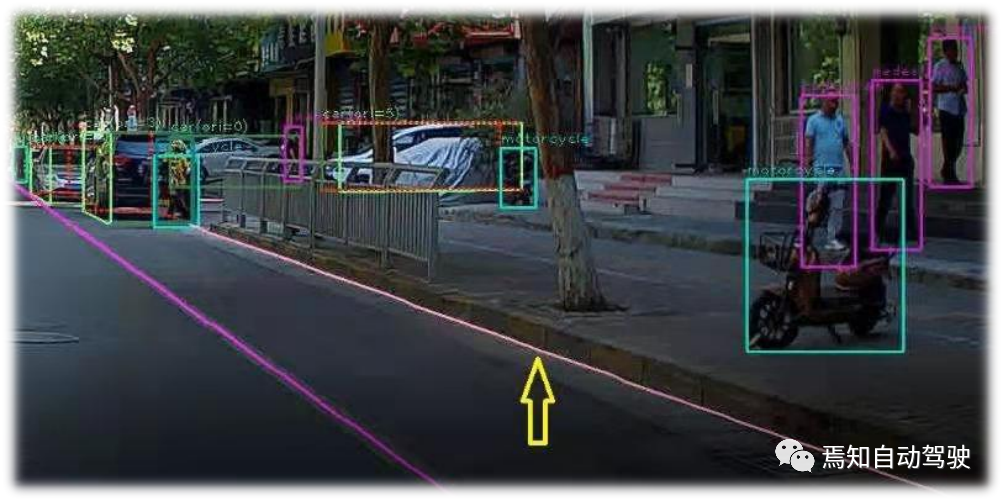
In addition, the side radar cannot effectively detect the side lane markings, cannot compensate for the blind spots caused by the limited detection of the forward-looking camera, and cannot provide support for the side fusion Freespace.
Camera solution basic infrastructure
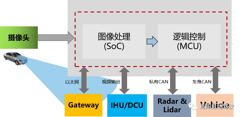
The next-generation autonomous driving system’s basic infrastructure diagram is shown below. Among its key elements, the image processing Soc section mainly covers the sensor input image processing ISP and target fusion of the camera image. Of course, radar or lidar can also use raw data as input information for target input. The logic control unit MCU is responsible for processing the target fusion results of the Soc and inputting them to the motion planning and decision control model unit for processing. The results of its processing are used to generate vehicle control commands to control the vehicle’s horizontal and vertical motion.
The next-generation autonomous driving system’s typical sensor architecture diagram for camera-only solutions is shown below, and the corresponding performance of the sensing load is explained below.

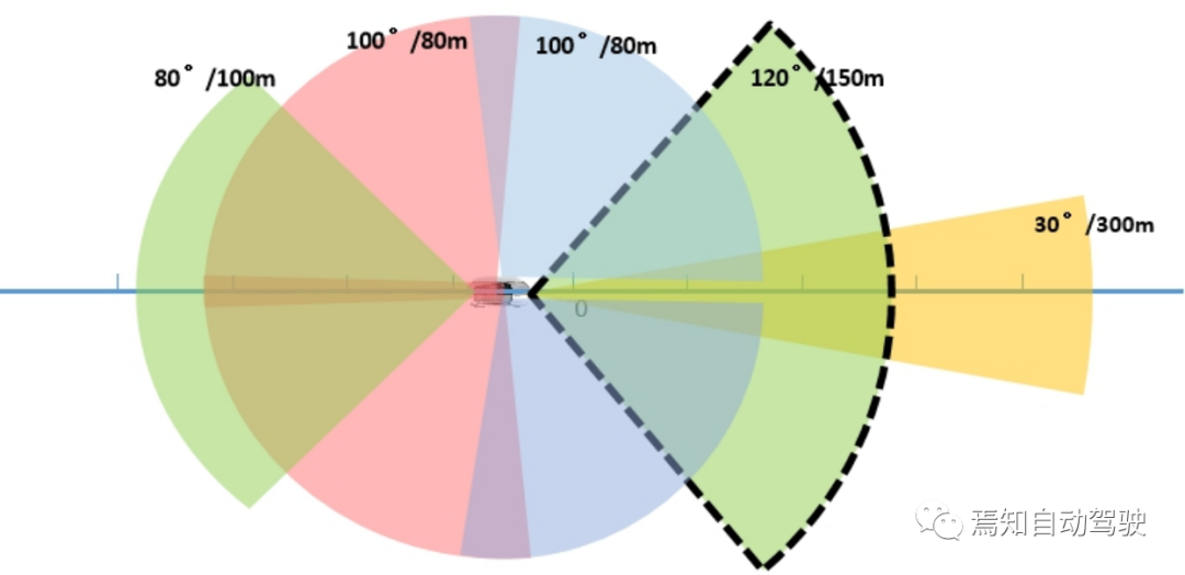
In addition to the basic indicators mentioned above, the camera’s image resolution and frame rate also need to be carefully considered. After solving the computing power and bandwidth problems of the central controller for autonomous driving, the higher the camera’s image resolution, the better. Considering the specific scene problems that need to be solved during vehicle driving, it is generally better to have a higher resolution for the forward detection process. The currently promoted resolution for forward-facing camera detection is 8 million pixels. The target of the side-view camera detection is generally the side lane target. The scene matching library for the side lane is generally less focused on autonomous driving scenes, and the requirements for the side detection distance are also closer than those for forward detection. Therefore, the resolution requirements for side detection can be slightly lower than those for forward-looking cameras. It is recommended to use a 2 million pixel camera to meet the requirements. Of course, if cost and processing efficiency are not considered, sensor load can refer to the forward-facing camera solution.
Image processing software architecture of SocFor image processing software models in the automotive industry, they are mainly implemented in Soc chips. The software modules include image signal processing (ISP), neural processing units (NPU), central processing units (CPU), codec units, MIPI interface outputs, and logic operation MCU interface outputs.
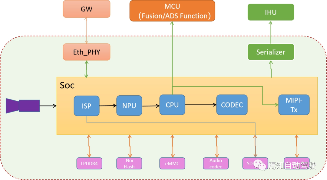
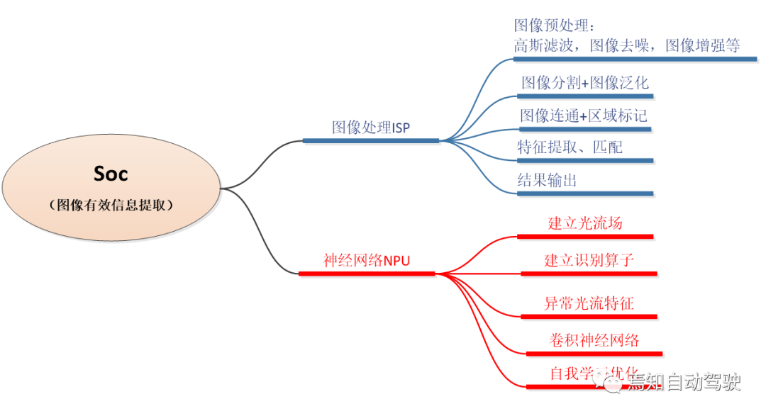
Among these computation units, ISP and optimized NPU for neural networks are the most computationally intensive.
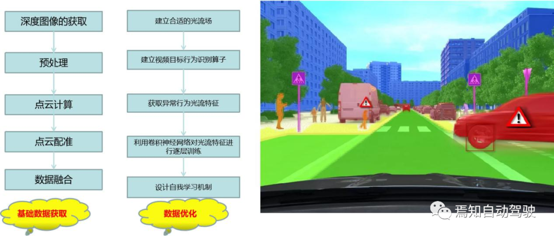
The optimized results are used for generating basic image information on one hand, and for comprehensive information processing and allocation to the central processing unit CPU on the other hand. They are also applied to the codec unit for outputting decoded images through the MIPI interface to video and audio systems for display. At the same time, the results after environmental semantic analysis are input to the ADAS logic control node MCU, which can integrate environmental information data sources, such as millimeter-wave radar, LIDAR, panoramic cameras, and ultrasonic radar, to generate integrated environmental data. These data are finally used for vehicle function application control.
Of course, if considering the input of some information into other intelligent control units for information fusion in the intelligent driving assistance control, the generated results need to be input through the Ethernet into the gateway, which will forward the information to other units, such as the intelligent parking system and the human-machine interaction display system.
Also, if considering the accident tracing in the process of automated driving, some information processed by the Soc will be input into the storage card, or directly uploaded to the cloud or background monitoring through TBox.
Hardware Module Design Requirements for Camera
In the traditional surround-view scheme, the perception of the surrounding environment of the vehicle is achieved using fish-eye cameras with a FOV larger than 180 degrees. With the development and promotion of the L3 platform in the industry, many manufacturers have also attempted to promote peripheral and rear perception schemes based on surround-view fish-eye cameras. In general, surround-view fish-eye camera schemes cannot meet the requirements of true L3+ autonomous driving platforms. The main reasons are as follows:
- The installation position of the traditional surround-view cameras is mainly for providing a visual range of 5-10 meters in front, rear, left, and right. However, the positions of left-front, right-front, left-rear, and right-rear concerned in L3 autonomous driving belong to the image splicing range of the camera, and the perception accuracy is affected by splicing.- Surround view cameras cause significant distortion in images of distant and close objects, making it difficult to accurately predict the 3D posture, size, and motion trajectory of objects in the original image. In the corrected image, perception accuracy is reduced due to distortion.
- Surround view cameras are generally used to perceive the road at close range and have a low pitch angle.
Therefore, the explosion diagram of the camera hardware module with L3+ level automatic driving capability is as follows. The main factors considered in the corresponding performance design are: image transmission method, output resolution, frame rate, signal-to-noise ratio, dynamic range, exposure control, gain control, white balance, minimum illumination, lens material, lens optical distortion, module depth of field, module field of view, rated operating current, operating temperature, storage temperature, protection level, dimensions, weight, functional safety level, and connector/wiring impedance.
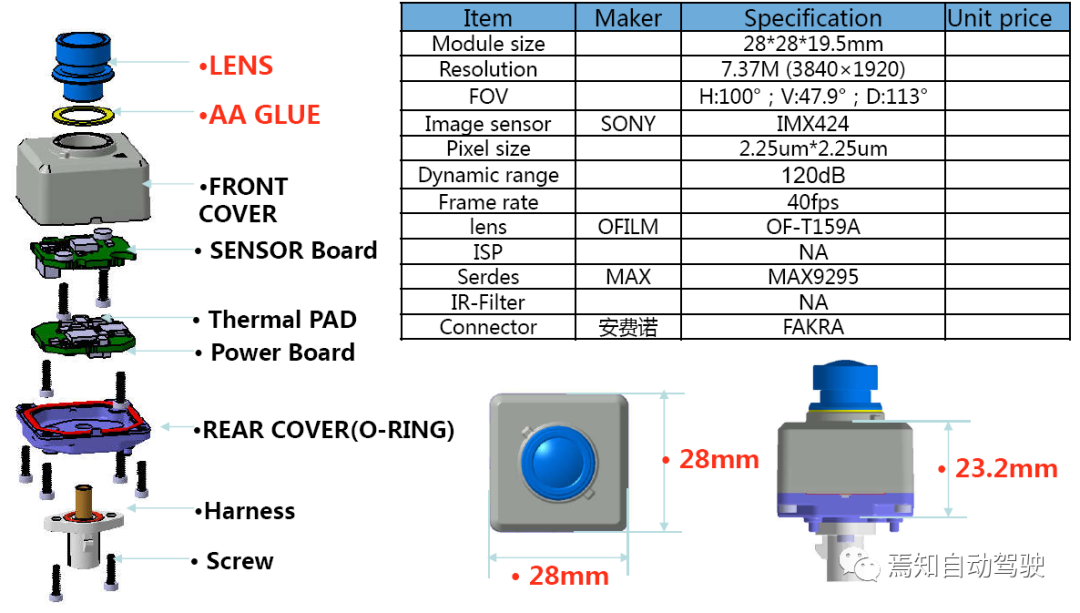
The installation position of the camera and its configuration largely determine the range and accuracy of visual perception. Based on an understanding of the current operating design domain (ODD), the side-view camera configuration must not only meet vehicle regulation standards for signal-to-noise ratio and low-light performance, but also the following parameter requirements:

Visual information is input through an optical lens and processed through multiple stages to the final perception algorithm detection result. Many linear and nonlinear factors affect the result, and there is currently no unified formula in the industry to express the camera configuration and final detection result. To conceptually explain the main methods considered in camera configuration, below is a chart for the sensor pixel output of a typical camera in different scenarios, based on the type and distance of the detected object:
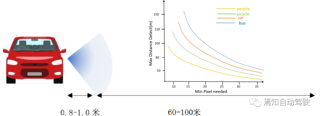
In addition, regarding the camera layout, the main points of concern include water and dust resistance levels and whether there are parts that can obstruct detection within its detection range. Therefore, front-view cameras are generally placed near the rearview mirror, using a certain bracket to secure them internally, which is not generally complicated. For side-view cameras, since they generally need to be placed on the side of the vehicle, the recommended position is usually based on the layout position of the panoramic camera, placed below the outside rearview mirror or even on a dedicated fender. This places new requirements on the size, dimensions, weight, and other hardware module aspects of the camera itself. Below is a draft of a basic and typical camera installation scheme, including the recommended installation position:
Based on the current known information and some experience in related development, cross-perspective can ensure that the relatively narrow-angle camera covers the near and far distance of the vehicle body effectively. The functions of the front and rear sides are slightly different, with the side front detecting the scene. The installation position and pitch angle can be high, and the FOV is slightly wide. The Side rear mainly detects the vehicles in the rear and near lanes, which can be used for high-speed entrance and exit of the lane change. The pitch angle can be low, and the yaw angle is closer to parallel with the centerline of the vehicle. The FOV is slightly narrow. Specific parameters may need to be adjusted during the design process.
Summary
The requirements for sensors in the next generation of autonomous driving systems are further increased, mainly reflected in the camera perception system. Among them, a key consideration is whether the autonomous driving domain controller’s computing power and bandwidth can fully meet the requirements of camera sensors. In addition, the basic parameters of the camera, such as detection range, angle, resolution, frame rate, and other basic elements, are also a key focus. In terms of its hardware, the setting module-related content needs to focus on elements such as signal-to-noise ratio, heat generation, size, dimensions, waterproof and dustproof performance, etc., to ensure that the placement position can meet its detection performance requirements. Finally, regarding the detection ability of the new type of camera, there is a significant leap in its effectiveness in environmental detection results. For example, improving the accuracy of lane lines C0, C1, C2, C3 comprehensively provides support for LKA, LCC, etc. through larger curved paths. Improving the recognition distance and recognition angle of each adjacent lane provides further and more accurate input for the path planning of the lane change.
This article is a translation by ChatGPT of a Chinese report from 42HOW. If you have any questions about it, please email bd@42how.com.