Automatic Transmission Control: How TCU Application Software Works
Author: Confused Zhen
If you have learned to drive, you should have a concept of starting and shifting, such as stepping on the clutch pedal and manually shifting gears. However, with automatic transmission, you don’t need so many operations. Just put the gear selector in PRND mode and press the accelerator pedal to speed up the car, or brake to slow down. But how is this achieved?
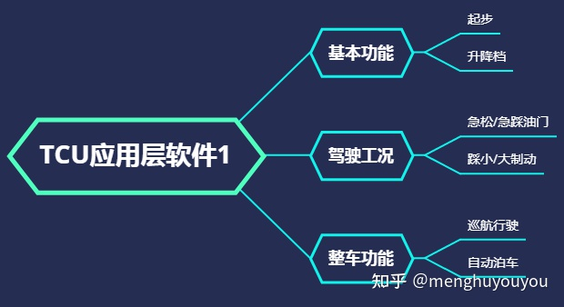
In this article, we will reveal how the automatic transmission is automatically controlled through the TCU application layer software. Therefore, based on the previous article, “Fundamentals of Automatic Transmission Control: TCU Software Development Part 1”, this article will first introduce the backbone of TCU software architecture from the most basic functions of automatic transmission, then demonstrate how TCU application layer software is continuously improved through typical driving conditions, and finally understand how TCU cooperates with other ECUs through some popular vehicle functions.
This article will introduce how TCU application layer software automatically controls the transmission through a dual-clutch automatic transmission (DCT).
Basic Functions
1.1 Starting and Shifting
We know that the basic functions of the transmission are mainly starting and shifting. So how does DCT achieve starting?
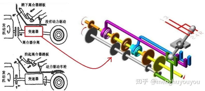
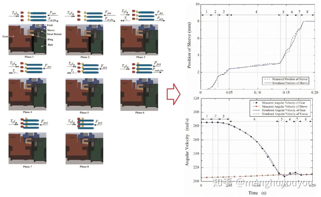
As with starting a manual transmission, for DCT, the engine is first disconnected from the transmission, then the gear is shifted to 1st gear, followed by engaging the clutch. So how does the TCU application layer software control these actions? Taking shifting as an example, the control is shown below:
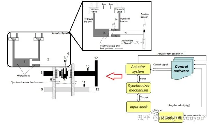
The TCU application layer software controls the solenoid valve to regulate the flow of oil entering the hydraulic cylinder, thereby controlling the displacement of the gear selector hydraulic cylinder piston. Because the piston is connected to the shift fork and the shift fork is connected to the synchronizer mechanism, controlling the movement of the piston can control the shifting process. The logic for clutch control is similar to this.
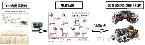
In summary, the TCU application layer software controls the electro-hydraulic system (which actually requires support from TCU lower-level software and hardware drivers to control the solenoid valve), and then the electro-hydraulic system is connected to the clutch and gear selector via the piston, finally applying control force to the dual-clutch and shift synchronizer to achieve the functions of starting and shifting.
1.2 Basic Architecture of TCU Application Layer Software
At this point, you may have some questions, such as:- How does the TCU application software determine if it’s starting or shifting?
- What does the TCU application software use to control the electrohydraulic system?
Next, we will introduce the basic architecture of the TCU application software by using these two questions as examples. Let’s start with the input of the TCU application software. Imagine a vehicle with DCT that is accelerating in 2nd gear. What information can we extract from this situation?
-
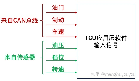
Throttle and vehicle speed, which come from other ECUs in the vehicle, such as the ECM (Engine Control Module) or VCU (Vehicle Control Unit), and are usually sent to the TCU via the CAN bus. The TCU’s underlying software receives and processes the signals before passing them to the application layer software.
-
Gear position, which comes from the gear position sensor. The TCU’s underlying software collects and processes the sensor data before sending it to the TCU application layer software.
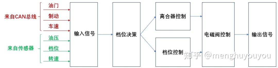
In addition, the TCU application software also receives more information from other sensors, such as the RPM sensor, temperature sensor, pressure sensor, etc. In general, the signals received by the TCU application software can be divided into two categories: those from other ECUs and those from sensors, as shown below:
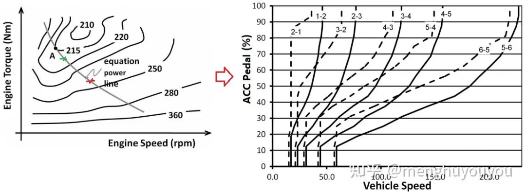
What is the use of these signals received by the TCU application software? For example, when the vehicle is accelerating in 2nd gear, it must shift to a higher gear, and the TCU application software will calculate the shift point based on the universal characteristics of the engine, taking into account fuel consumption, power, and other factors. When the vehicle speed reaches the shift point for 3rd gear, the TCU application software will shift to 3rd gear. This process is called gear position decision making.
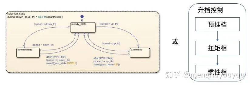
To shift gears, the TCU application software first preselects 3rd gear, then performs clutch swapping (torque phase), and finally performs RPM synchronization (inertia phase), as shown below:
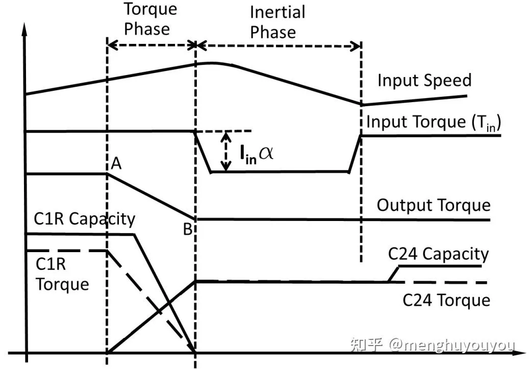
So how does the TCU application software control the gear shifting and clutch swapping? There are corresponding modules in the TCU application software for clutch control and gear control.
Essentially, clutch control calculates the clutch torque based on the following:


The gear control is mainly achieved by precise synchronization force control based on detailed analysis of the synchronizer engagement process, which is also the theoretical basis mentioned in the previous article. Of course, practical applications are not limited to this, and they also involve a lot of engineering experience and knowledge.
When the required clutch torque and synchronization force are calculated:

It is necessary to realize it through the electro-hydraulic system. That is, the TCU application layer software will control the solenoid valve according to the characteristics of the clutch and solenoid valve, and send the control amount of the solenoid valve to the bottom layer software to achieve the final control.
This basically answers the two questions above and obtains the basic architecture of the TCU application layer software, as shown below:
The above roughly describes a forward development process, and also reveals the role of theory. Of course, the actual TCU application layer software is much more complex than this. In terms of software functions, in addition to considering the basic functions from a theoretical perspective, many driving conditions and vehicle functions need to be considered from an engineering perspective.
Driving conditions
For example, in the process of shifting from 2nd to 3rd gear mentioned above, if the brake is suddenly applied during the clutch exchange process, as shown in the red point 1 or orange point 2 in the figure below, how should it be handled?
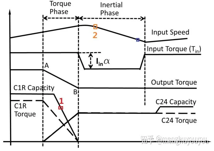
Should it jump to downshift processing or continue with upshift control? If it continues with upshift control, how should it be handled? This is intended to illustrate that the development of TCU application layer software needs to fully consider the driving condition factors and cannot be answered without addressing the problem.
Another example is the process of shifting from 6th to 7th gear with light throttle. If the throttle is suddenly stepped down at point 1 or point 2, how should it be handled? This should trigger a power downshift, as shown below, but how to switch from upshifting specifically?
OK! The following are just a few driving conditions that may arise during vehicle operation. There are actually many more, so the TCU application software must take all of these into account in order to ensure control quality.
Vehicle Functions
As one of the ECUs in the vehicle, the TCU naturally participates in some vehicle functions, such as adaptive cruise control and automatic parking.
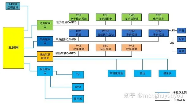
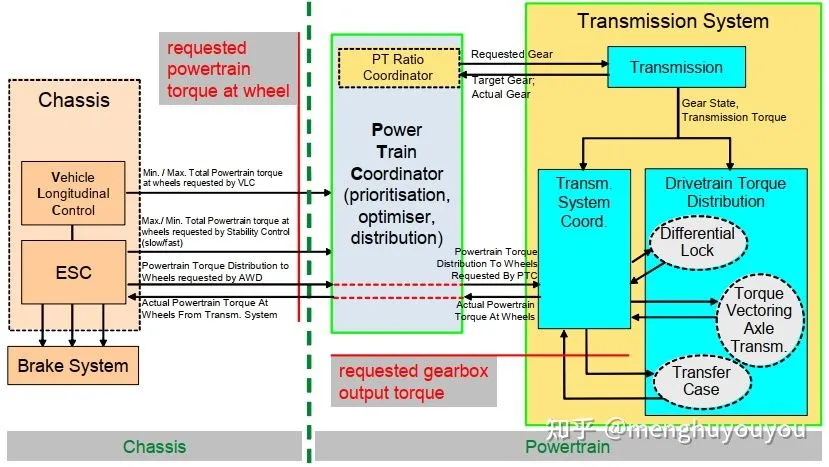
Simply put, whenever there is longitudinal control of the vehicle, the automatic transmission is generally required to participate in controlling the gear position and the torque output to the vehicle wheels. Therefore, the TCU application software includes controls for these vehicle functions. The basic idea of how it interacts with other ECUs to achieve these vehicle functions is shown below:
Summary
The TCU application software essentially controls the automatic transmission based on theoretical foundations, actual driving conditions, and vehicle functions. By grasping this main thread and studying the subtleties of the details as time accumulates, the software can be mastered. I believe that this is also essentially how it works for other ECU application software.
Reference
[1] Dynamic Analysis and Control System Design of Automatic Transmission [book]
[2] Development and Analysis of Synchronization Process Control Algorithms in a Dual Clutch Transmission [D]
[3] Modelling and analysis of the synchronization process for a wet dual-clutch transmission [J][4] Explanation of application interfaces of the powertrain domain.pdf
This article is a translation by ChatGPT of a Chinese report from 42HOW. If you have any questions about it, please email bd@42how.com.