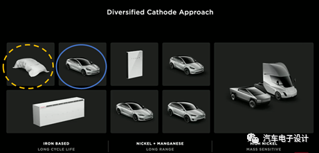
Recently received a shared photo and briefly discussed the compatibility transformation, which is actually consistent with the previous idea. I think the 2.5 million-dollar car Elon Musk did not mention in Battery Day is most likely relying on this LFP battery. From the perspective of low-cost paths, there are two parallel routes, one based on long-life LFP and the other based on weight-sensitive battery design.
Overview of LFP Design
1) Module Dimensions
Due to Tesla’s overall package design, the design height is only about 120 mm, so the corresponding module height is only 81 mm. Therefore, in the LFP design, compatible design is also adopted.
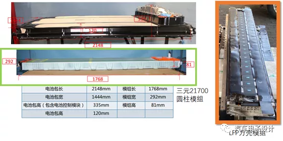
Two different configurations are used here, with 25 cells and 28 cells, totaling 106 cells, to make two module specifications compatible with the original ternary module design.
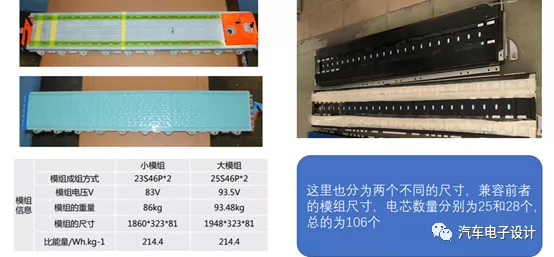
In fact, there are several features in the above picture. The connection outlet of the water-cooling plate has a relatively long distance, and the overall size is kept in size compatibility (more than 4 cells can be installed actually). A certain gap is retained between the cells here, and the end plate is a strong design choice to allow so many cells to maintain a certain pressure.
Note: my understanding is that if this design replaces LFP with ternary NCM 811 and adds thermal insulation materials, there is enough space. In addition to the LFP version, the long-distance version of the shell cell can also be designed in this way, which is probably a matter for 2021.

In this side view of the end plate, we can see the complete standard design. The water-cooling plate is integrated on the bottom of the module, and there is a complete structure outside to cooperate with this water-cooling plate. On the one hand, it allows the module to have sufficient mechanical strength, and on the other hand, it also has sufficient insulation distance. The water-cooling plate is mainly used for low-temperature heating in LFP, while in subsequent NCM versions, the cooling problem needs to be solved. The challenge of designing 82 mm thick cells is how to achieve 250 kW super fast charging.In this design, due to the height of the square shell battery cell and the corresponding sampling and insulating board of the module, Tesla adjusted the layout of the sampling board of the CMU. It is no longer in the original part of the module and is extended by using a flexible circuit board. Only the part that needs to be cut is shown here.

There is also enough distance left in the Y direction dimension. As shown in the figure below, a complete fixed structure is used to cover the mounting points of the module and the fixing points of the previous three cylindrical modules one by one.
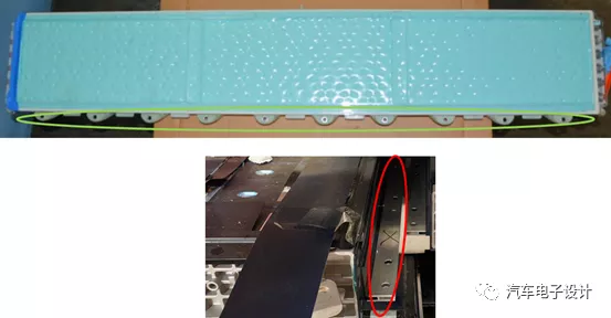
This next figure is more clear, the square shell design reduces the use of a lot of thermal filling glue. The black part of the side plate and the water cooling plate are fixed together through the structure.
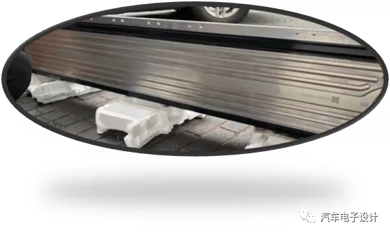
Strictly speaking, this is a design that began to appear more frequently in mass-produced models in 2020, where water cooling plates are embedded in soft pack and square shell modules, and the biggest advantage is to reduce the requirements for size tolerance. It also reduces the use of thermal adhesive in the process from battery cells to water cooling plate, while also meeting the gradually increasing design requirements for fast charging in the next generation.
Conclusion
I think this design is worth learning from. Before the next generation breaks through the CTC of module design, this design concept can still balance the requirements of cost, maintainability, and energy density very well.
This article is a translation by ChatGPT of a Chinese report from 42HOW. If you have any questions about it, please email bd@42how.com.
